ESD Precautions
ESD Precautions
Please be careful attention when using or handling LCM, must comply with ESD protection actions. It is necessary to take care if LCM has wrong contact or I/O reverse install at assembly. This will be very easy to cause LCM power sequence signal error to occur EOS shock damage to IC itself in a very short time.
Below are few possible reasons to cause IC damage, please be more careful.
(1) Electric static damage : LCM driver IC is CMOS type, must be careful of ESD discharge to cause CMOS IC damage.
- Do not remove the LCM from its anti-static bag until it’s to be assembled. LCM’s are individually packaged in bags specially treated to resist static electricity. When storing, keep the LCM packed in the original bags, or store them in a container processed to be resistant to static electricity, or in an electric conductive container.
- Be sure to ground your body when touch/handling LCM.
- Before removing LCM from ESD protect bag, be sure the module and your body at the same electric potential.
- Welding connector on LCM, must notice welding pad has not damage or broken.
- Tools required for assembling, such as soldering irons, must be properly grounded. Make certain the AC power source for the soldering iron does not leak. When using an electric screwdriver to attach LCM, the screwdriver should be of ground potentiality to minimize as much as possible any transmission of electromagnetic waves produced sparks coming from the commutator of the motor.
- Operator’s clothes or working chair/bench should connect to ground.
- Attention to the humidity in working area, do not conduct assembling and other work under dry conditions. This could reduce electric static to be occurred. A relative humidity of 50%~60% is recommended.
- The LCD module is coated with a protective film to protect the display surface. Exercise care when peeling off this protective film since static electricity may be generated.
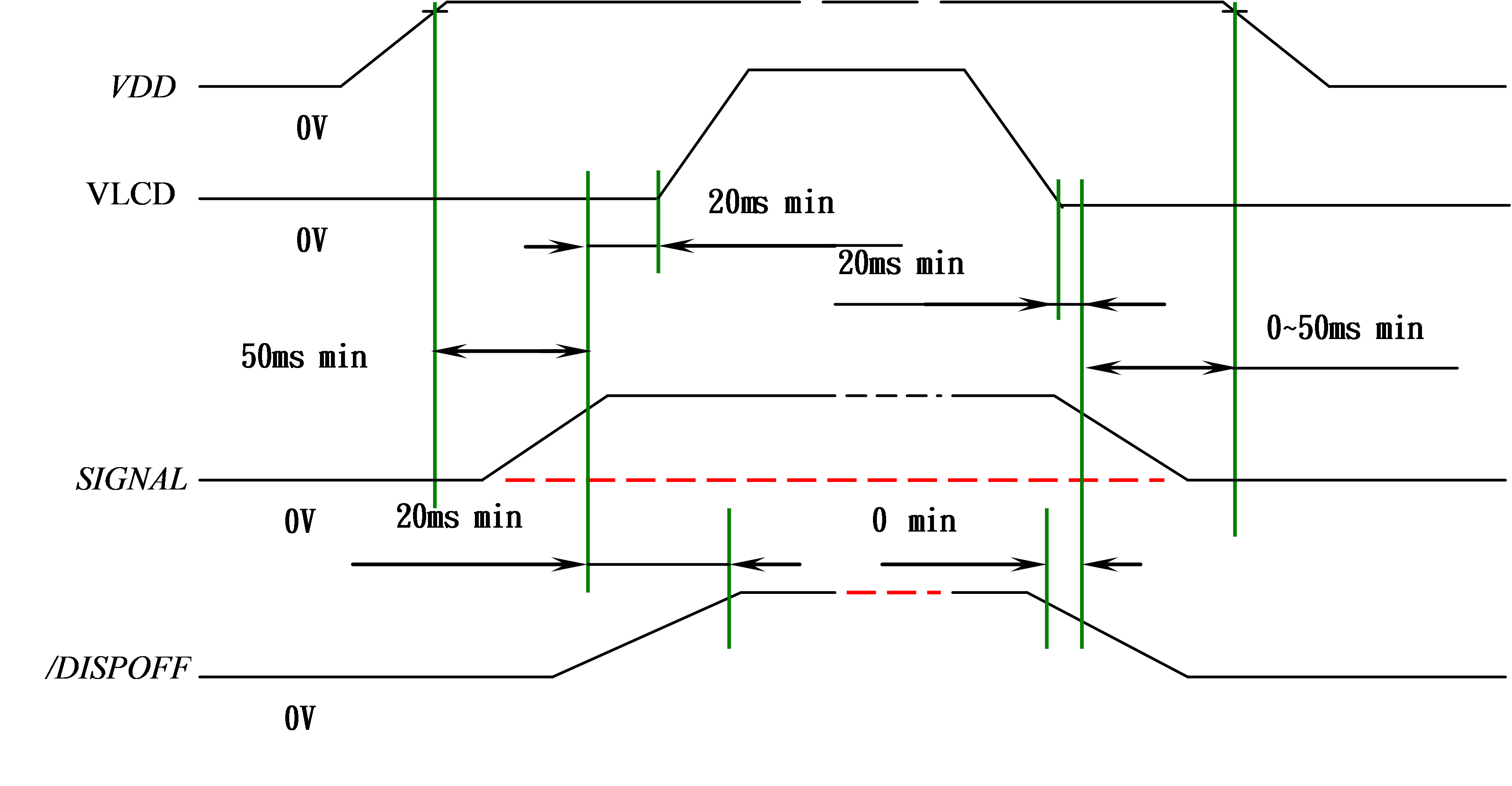
(2) Power sequence: This is general electric system standard. LCM requires Power sequence setting as below(shown as SPEC), it is to prevent latch up under incorrect Power sequence timing to have IC damage.